Have you ever found yourself in the middle of a project, whether it's rebuilding an engine, calibrating a telescope, or even just setting up a precise woodworking jig, and wished for a simple, accurate, and readily available tool to measure angles with absolute certainty? Trust me, you're not alone. The world of precision work often feels like it's guarded by expensive, specialized equipment, but what if I told you there's a powerful, versatile, and incredibly accessible tool that you can literally print out and use right now? Enter the humble yet mighty printable degree wheel.
I remember my first foray into engine building – a classic air-cooled VW engine that seemed to have more mysteries than an ancient scroll. I was attempting to degree the camshaft, a critical step for maximizing performance, and I was utterly lost. The expensive digital degree wheel I'd borrowed felt clunky, and the instructions were for a different engine type. Frustration mounted. Then, an old-timer at the local machine shop winked and handed me a laminated piece of paper, perfectly circular, with crisp markings. "Here, son," he said, "sometimes the old ways are the best ways. Just print one of these bad boys out, glue it to some cardboard, and you'll be set." And just like that, a simple printable degree wheel became my secret weapon, demystifying complex engine timing and opening up a world of DIY precision. That day, I learned that sometimes the most powerful tools are the ones you create yourself, tailored exactly to your needs.
This isn't just a guide; it's an invitation to unlock a new level of accuracy and confidence in your projects. We're going to dive deep into everything you need to know about the printable degree wheel, from its fundamental uses to advanced applications, how to create your own, common pitfalls to avoid, and even some clever hacks that will make you wonder how you ever lived without it. Whether you're a seasoned mechanic, a curious hobbyist, a dedicated educator, or just someone who appreciates the beauty of perfect angles, this comprehensive resource is designed to empower you. So, grab your printer, a pair of scissors, and let's embark on this journey to precision together.
---
Table of Contents

- [The Heart of Precision: What Exactly is a Printable Degree Wheel?](#the-heart-of-precision-what-exactly-is-a-printable-degree-wheel)
- [Your DIY Workshop Buddy: Creating Your Own Printable Degree Wheel](#your-diy-workshop-buddy-creating-your-own-printable-degree-wheel)
- [Engine Timing Mastery: Using Your Degree Wheel for Automotive Applications](#engine-timing-mastery-using-your-degree-wheel-for-automotive-applications)
- [Beyond the Garage: Creative & Unexpected Uses for Your Degree Wheel](#beyond-the-garage-creative--unexpected-uses-for-your-degree-wheel)
- [Achieving Pinpoint Accuracy: Calibration & Best Practices for Your Degree Wheel](#achieving-pinpoint-accuracy-calibration--best-practices-for-your-degree-wheel)
- [The Digital Age vs. DIY: When to Choose Printable vs. Digital Degree Wheels](#the-digital-age-vs-diy-when-to-choose-printable-vs-digital-degree-wheels)
- [Troubleshooting & Common Snags: What to Do When Your Degree Wheel Isn't Cooperating](#troubleshooting--common-snags-what-to-do-when-your-degree-wheel-isnt-cooperating)
- [Level Up Your Projects: Advanced Modifications & Customizations for Your Printable Degree Wheel](#level-up-your-projects-advanced-modifications--customizations-for-your-printable-degree-wheel)
- [Teaching & Learning: Educational Applications of the Printable Degree Wheel](#teaching--learning-educational-applications-of-the-printable-degree-wheel)
- [How to Choose the Best Printable Degree Wheel for Your Needs](#how-to-choose-the-best-printable-degree-wheel-for-your-needs)
- [Common Pitfalls to Avoid](#common-pitfalls-to-avoid)
- [Advanced Tips for Experts](#advanced-tips-for-experts)
- [Conclusion](#conclusion)
---
The Heart of Precision: What Exactly is a Printable Degree Wheel?
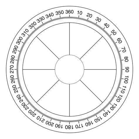
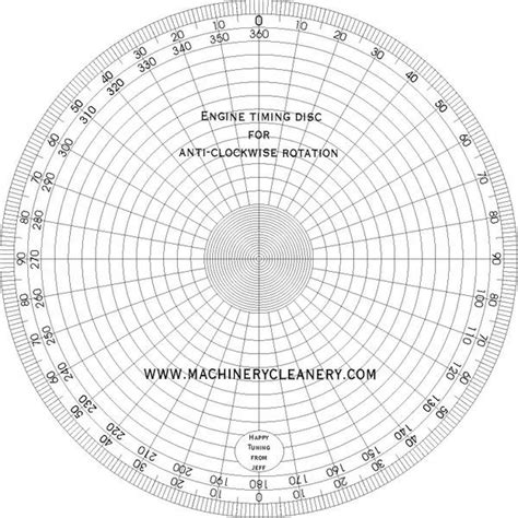
At its core, a printable degree wheel is a circular protractor, typically marked with 360 degrees, designed to be printed from a digital file. Its genius lies in its simplicity and versatility. Unlike a standard protractor, which is often used for drawing angles on flat surfaces, a degree wheel is primarily designed for measuring rotational angles or setting precise angular positions on a rotating shaft or component. Think of it as a compass that tells you how far something has turned, not just which way it's pointing.
Why is this simple paper circle such a big deal? Because in many mechanical, scientific, and even artistic applications, the exact angular position of a component is absolutely critical. A few degrees off in engine timing can mean the difference between peak performance and a rough idle. An incorrect angle in a woodworking joint can compromise structural integrity. This is where the printable degree wheel shines – providing an inexpensive, readily available, and surprisingly accurate solution for these precise measurement needs.
Here are some key aspects that define and differentiate a printable degree wheel:
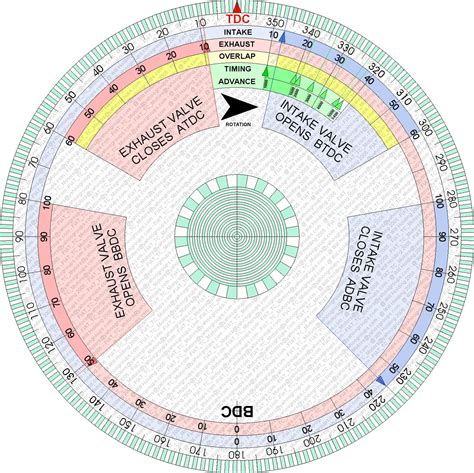
1. Fundamental Design: It's a circular scale, usually with a central pivot point, marked with degrees from 0 to 360. Some designs might have additional markings like BTDC (Before Top Dead Center) and ATDC (After Top Dead Center) for automotive use, or even fractions of a degree.
2. Accessibility: The "printable" aspect is its superpower. You don't need to order one, wait for shipping, or spend a fortune. A quick search online, a printer, and a few minutes are all it takes to have a functional tool in your hands. This democratizes precision, making it available to everyone from home mechanics to students.
3. Versatility: While often associated with engine work, its applications extend far beyond. Anywhere a rotational angle needs to be measured or set, a degree wheel can be adapted. It's a testament to simple mechanical principles.
4. Cost-Effectiveness: It's practically free. The only cost is ink, paper, and perhaps some laminating film or cardboard for durability. This makes it an ideal choice for one-off projects, educational settings, or as a backup tool.
5. Educational Value: For beginners, creating and using a printable degree wheel offers a hands-on lesson in angular measurement, precision, and the importance of accurate setup in mechanical systems. It’s a tangible way to understand abstract concepts.
6. Customization Potential: Because you're printing it, you have the option to scale it, add your own specific markings, or even design one from scratch to perfectly fit your unique project requirements. This level of personalization is something you rarely get with off-the-shelf tools.
7. Basis of Measurement: It provides a visual reference for rotational displacement. You fix the wheel to a rotating object (like a crankshaft) and use a stationary pointer to read the angle as the object turns. This fundamental process is key to many precise adjustments.
8. The "Why" of Precision: Using a degree wheel forces you to slow down and consider the exact angular relationship between components. This isn't just about getting a number; it's about understanding the mechanics at a deeper level. I've found that the act of carefully setting up a printable degree wheel makes me more mindful of the entire assembly process.
9. Historical Relevance: While modern tools exist, the principle of the degree wheel is ancient. Its continued use in its most basic form speaks to its timeless utility and fundamental importance in engineering and mechanics.
10. Problem-Solver: Need to set a precise ignition timing? The printable degree wheel is your friend. Want to understand how far your suspension arm moves through its travel? Grab a degree wheel. It solves a specific problem that many other tools either overcomplicate or can't address directly.
11. Analog Reliability: In a world of digital readouts that can fail or run out of battery, a well-made paper degree wheel is immune to such issues. Its reliability is in its simplicity – as long as it's readable, it works.
12. The "Aha!" Moment: For many DIYers, the first time they successfully use a degree wheel to accurately time an engine or align a component is a genuine "aha!" moment. It transforms a daunting task into a manageable, even enjoyable, process.
The printable degree wheel might seem like just a piece of paper, but it embodies the spirit of practical engineering and problem-solving. It's an indispensable tool for anyone who values accuracy and the satisfaction of a job well done.
---
Your DIY Workshop Buddy: Creating Your Own Printable Degree Wheel
One of the greatest appeals of the printable degree wheel is its DIY nature. You don't need to be a master craftsman or an engineering genius to create a perfectly functional one. In fact, the process itself is a mini-project that can be quite satisfying. Think of it as crafting a custom tool specifically for *your* needs, right in your own workspace.
Here’s a step-by-step guide to making your own workshop buddy, complete with tips and tricks I've picked up over the years:
1. Find the Right Template:
- Online Search: Start with a simple Google search for "printable degree wheel template" or "free degree wheel PDF." You'll find a plethora of options.
- Software Options: Many CAD or design software programs (even free ones like Inkscape) can generate degree wheels. Some even offer specific templates for automotive applications, like those for camshaft degreeing.
- Consider Scale: Look for templates that clearly state their intended size or are easily scalable. Some are designed for specific print sizes (e.g., A4, US Letter).
- My Recommendation: I always look for templates with clear, bold markings and a distinct 0/360-degree point. Finer subdivisions (e.g., 0.5 or 0.25 degrees) are a bonus if your project demands extreme precision.
2. Printing for Precision:
- Printer Settings: Ensure your printer is set to print at "actual size" or "100% scale," *not* "fit to page." This is crucial for accuracy.
- Paper Quality: Use good quality, thicker paper (e.g., cardstock, 65-80 lb) if possible. It will be more durable and less prone to warping or tearing. If only regular printer paper is available, don't fret – we have solutions!
- Color vs. Black & White: Black and white is perfectly fine. The key is contrast and clarity of the markings.
- Check for Distortion: After printing, quickly measure the diameter with a ruler and compare it to any specified dimensions on the template. Sometimes printers can slightly distort the image, though this is rare with modern devices.
3. Mounting for Durability and Rigidity:
- Cardboard Backing: For most applications, gluing your printed degree wheel to a piece of sturdy cardboard (like from a cereal box or a moving box) is perfect. Use spray adhesive or a good quality craft glue, ensuring it’s spread evenly to avoid bubbles.
- Laminating: If you want something more durable, especially for repeated use or in a greasy workshop environment, laminate it! You can use a home laminator or take it to a print shop. This makes it resistant to moisture and tearing. This is my go-to method; a laminated printable degree wheel feels almost professional.
- Plastic/Metal Backing: For truly heavy-duty use, you can glue it onto a thin sheet of plastic (like an old cutting board) or even aluminum. This might require stronger adhesives like epoxy.
- CD/DVD Method: A clever hack I once learned was to glue a smaller degree wheel onto an old CD or DVD. The central hole is often perfectly sized for many shafts, and the disc provides excellent rigidity.
4. Cutting with Care:
- Scissors vs. Craft Knife: For a perfectly circular cut, a craft knife (like an X-Acto knife) with a cutting mat and a compass-style circle cutter is ideal. If using scissors, take your time and follow the outline precisely. Any wobbles can introduce minor inaccuracies, especially if the wheel is small.
- Central Hole: Use a small drill bit (matching your mounting bolt/shaft size) for the central pivot point. Start with a tiny pilot hole and gradually increase the size if needed. A punch can also work for smaller holes. Ensure the hole is perfectly centered.
5. Creating a Pointer (Critical for Accuracy):
- Rigid Material: A pointer is essential. This can be a stiff piece of wire, a coat hanger, a thin metal rod, or even a precisely bent piece of thick cardstock.
- Secure Mounting: The pointer must be mounted rigidly to a *stationary* part of your setup, pointing directly at the degree wheel's markings. It should be as close to the wheel as possible without touching, to minimize parallax error.
- Sharp Tip: The tip of your pointer should be sharp and fine to allow for precise reading. I often file the end of a coat hanger wire to a fine point for this purpose.
6. Assembly and Mounting:
- Central Bolt/Shaft: Mount your finished degree wheel onto the rotating component (e.g., crankshaft snout, camshaft end) using a bolt or adapter that fits through the central hole. It must be securely fastened so it doesn't slip.
- Ensure Free Rotation: The wheel should rotate freely with the component without rubbing against anything else.
- Leveling (if applicable): For some applications, ensuring the degree wheel is perfectly perpendicular to the axis of rotation is important. Use a small level if necessary.
7. Testing and Refinement:
- Initial Spin: Gently rotate the component and observe how the degree wheel moves. Does the pointer stay consistent? Are the markings clear?
- Zeroing: We’ll cover this in more detail later, but the first step is always to establish your 0-degree reference point.
- Troubleshooting: If something feels off, recheck your mounting, pointer rigidity, and the clarity of your markings. Sometimes, simply reprinting on better paper or remounting can solve issues.
Creating your own printable degree wheel is more than just a cost-saving measure; it's an exercise in understanding the tools you use. The feeling of precision you get from a perfectly crafted and calibrated DIY degree wheel is incredibly rewarding.
---
Engine Timing Mastery: Using Your Degree Wheel for Automotive Applications
When it comes to automotive work, the printable degree wheel isn't just a handy accessory; it's a fundamental tool for achieving optimal engine performance and reliability. Engine timing, especially camshaft degreeing, is a black art to some, but with a degree wheel, it becomes a precise, repeatable science. It's how you ensure that your engine's valves open and close at *exactly* the right moment relative to the piston's position, maximizing airflow and combustion efficiency.
Here are the critical automotive applications where your printable degree wheel truly shines:
1. Camshaft Degreeing (The Big One):
- What it is: This is the process of precisely setting the camshaft's installed position relative to the crankshaft. Camshafts have specific lift and duration events (when valves open and close), and these need to occur at specific crankshaft angles for the engine to perform as designed.
- Why it's crucial: An improperly degreed camshaft can lead to reduced horsepower, poor idle, low vacuum, and even engine damage. Even a high-performance cam won't deliver if it's not timed correctly.
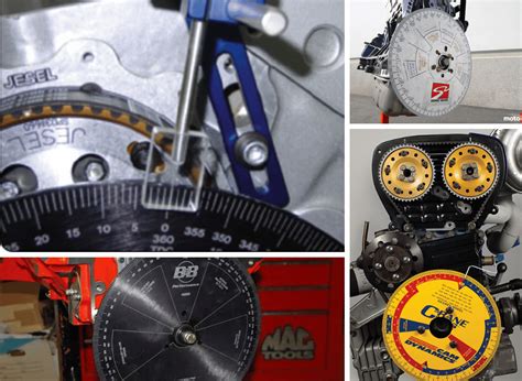
- How your degree wheel helps: You mount the degree wheel to the crankshaft, establish Top Dead Center (TDC) for cylinder #1, and then use a dial indicator on the valve retainer to measure valve lift at specific crankshaft angles. This allows you to match the actual valve events to the camshaft manufacturer's specifications.
- Personal Scenario: After building a custom engine for a drift car, I spent an entire weekend meticulously degreeing the camshafts with my homemade printable degree wheel. The engine fired up beautifully, pulled hard through the rev range, and idled perfectly. Without that precise setup, all the expensive parts would have been wasted. It’s the difference between a good engine and a *great* engine.
2. Finding True Top Dead Center (TDC):
- The Foundation: Before any timing work, you need to find the absolute mechanical TDC of cylinder #1 (or any cylinder you're working on). The timing marks on your harmonic balancer aren't always accurate, especially on older or rebuilt engines.
- Method: You'll use a piston stop tool (a bolt that threads into the spark plug hole and limits piston travel) along with your degree wheel. Rotate the engine until the piston hits the stop on the upward travel, note the degree wheel reading. Then rotate it backward until it hits the stop on the downward travel, and note that reading. True TDC is exactly halfway between these two points.
- Accuracy: This method, combined with a precise printable degree wheel, is far more accurate than relying on factory marks alone.
3. Ignition Timing Verification (Older Engines):
- Initial Setup: While a timing light gives dynamic timing, a degree wheel can be used for static timing or to verify the accuracy of your timing marks.
- Procedure: Once TDC is found, you can rotate the engine to a specific number of degrees Before Top Dead Center (BTDC) and physically check if the ignition system (e.g., distributor points opening) is firing at that precise point.
- Benefit: Great for troubleshooting or setting up engines without electronic ignition.
4. Crankshaft Angle Measurement:
- Beyond Camshafts: The crankshaft is the heart of the engine's rotation. Knowing its exact angular position is key for various diagnostics and adjustments.
- Applications: Checking crank sensor alignment (if applicable), measuring connecting rod angles, or even just understanding piston travel at different points in the stroke.
- The printable degree wheel provides a direct visual readout of this critical rotation.
5. Valve Lift Measurement at Specific Angles:
- Detailed Analysis: For performance enthusiasts or engine builders looking to optimize, you can use the degree wheel to measure actual valve lift at every few degrees of crankshaft rotation.
- Cam Profile Verification: This allows you to plot the actual valve lift curve and compare it against the camshaft manufacturer's specifications, identifying any discrepancies or wear.
- Spring Clearance Checks: Ensure there's enough clearance between the valve spring and other components throughout its travel.
6. Understanding Overlap and Lobe Separation:
- Camshaft Characteristics: Overlap (when both intake and exhaust valves are open) and Lobe Separation Angle (LSA) are crucial cam design parameters.
- Visualizing with the Wheel: By mapping out the valve opening and closing points on your printable degree wheel, you gain a clear visual understanding of these characteristics and how they affect engine behavior.
- Real-world application: I once had a tough time understanding why a certain cam made an engine so "choppy" at idle until I charted its overlap on a degree wheel. The sheer duration and overlap explained everything!
7. Advanced Engine Diagnostics:
- Relative Compression Testing: While usually done with a gauge, understanding crankshaft angle can aid in more precise relative compression analysis, looking for anomalies at specific points in the cycle.
- Injector Timing (Diesel): For some diesel engines, precise injector timing relative to crankshaft angle is vital for optimal combustion and emissions.
8. Flywheel/Flexplate Marking:
- Custom Applications: If you're adapting an engine or transmission and need to create new timing marks on the flywheel or flexplate, your printable degree wheel is the perfect reference.
- Procedure: Find TDC accurately, then mark your desired timing points (e.g., 10° BTDC) directly onto the rotating assembly using the degree wheel as a guide.
9. Distributor Phasing:
- Spark Delivery: For engines with distributors, ensuring the rotor is pointing directly at the cap terminal when the spark plug fires is crucial for maximum energy transfer.
- Precise Adjustment: The degree wheel allows you to rotate the engine to the exact firing point for a cylinder and then check/adjust the distributor's rotor position.
10. Torque Angle Specifications:
- Modern Fasteners: Many modern engine bolts (e.g., head bolts, main cap bolts) require a specific torque *plus* an additional angle of rotation.
- Using the Wheel: After torquing, you can use the degree wheel to accurately apply the specified additional angle, ensuring proper fastener stretch and clamping force. This is incredibly important for critical engine components.
- My Subjective Tip: For torque-to-angle fasteners, a good, rigid printable degree wheel is often easier to use and more reliable than many expensive digital angle gauges, especially in tight spaces.
The printable degree wheel transforms complex engine timing tasks into manageable, precise steps. It’s a must-have for anyone serious about engine building, restoration, or performance tuning.
---
Beyond the Garage: Creative & Unexpected Uses for Your Degree Wheel

While the automotive world often claims the printable degree wheel as its own, its fundamental utility as a precise angular measurement tool opens up a surprisingly vast array of applications far beyond the confines of a garage. It's a testament to the power of simple geometry and the ingenuity of makers everywhere. Here are some creative and unexpected ways this versatile tool can elevate your projects:
1. Astronomy and Telescope Alignment:
- Equatorial Mounts: For amateur astronomers, precisely aligning an equatorial telescope mount to the celestial pole is crucial for accurate tracking of stars and planets. A custom printable degree wheel can be used to set the latitude angle with greater precision than built-in scales, especially on budget mounts.
- Setting Circles: You can create your own setting circles for manual telescopes, allowing you to locate celestial objects by their Right Ascension and Declination coordinates.
- My Anecdote: I once helped a friend build a DIY tracking platform for astrophotography. We used a large, custom-printed degree wheel to precisely calibrate the motor's rotation rate against the Earth's rotation, resulting in surprisingly sharp, long-exposure star trails.
2. Woodworking and Joinery:
- Compound Miter Angles: When cutting complex angles for crown molding, picture frames, or furniture joints, setting the saw's bevel and miter angles precisely is key. A printable degree wheel can be taped to the saw blade or fence to verify and fine-tune angles beyond what the saw's built-in scales might offer.
- Dovetail and Box Joints: For hand-cut joinery, a small degree wheel can help lay out precise angles for pins and tails, ensuring tight, professional-looking joints.
- My Subjective Tip: For woodworking, I prefer a larger diameter degree wheel because even small errors at the center become significant at the edge of a board.
3. Art, Design, and Craft Projects:
- Mandala Creation: Artists creating intricate mandalas or geometric patterns can use a degree wheel to ensure perfect radial symmetry for their designs.
- Paper Crafting: For pop-up cards, origami, or paper sculpture, precise angle cuts and folds are essential. A small degree wheel can guide these measurements.
- Quilting and Fabric Arts: When designing complex quilt patterns or cutting fabric pieces that require specific angles, a degree wheel can be a lifesaver for accuracy.
4. Robotics and Automation:
- Servo Motor Calibration: In robotics, accurately positioning servo motors is vital. A small printable degree wheel attached to a servo horn can help calibrate its range of motion and identify exact angular positions.
- Linkage Design: When designing mechanical linkages or arms, understanding the angular travel of each joint is critical. The degree wheel provides a visual aid for this.
5. Education and STEM Projects:
- Physics Experiments: Demonstrating rotational motion, torque, angular velocity, and pendulum swings becomes much clearer with a visible, accurate degree wheel.
- Geometry Lessons: It's a fantastic hands-on tool for teaching angles, circles, and trigonometry in a practical context. Students can build their own and see math come to life.
- Engineering Design: For high school or college engineering projects, students can use the degree wheel for rapid prototyping and testing of mechanical designs.
6. Photography and Videography:
- Pano Head Calibration: For creating panoramic photos, a nodal slide and a rotating base (pano head) need precise angular increments. A custom printable degree wheel can be used to mark these increments for consistent overlaps.
- Time-Lapse Rigs: When building DIY time-lapse motion control rigs, a degree wheel can help calibrate the rotational steps for smooth, consistent movement over time.
7. DIY Prototyping and Mechanism Design:
- Gear Ratios: When experimenting with different gear and pulley combinations, a degree wheel can help visualize and verify the resulting rotational relationships.
- Cam Mechanisms: Designing simple cam mechanisms for automata or small machines often requires setting precise lift and dwell angles.
8. Home Improvement and Renovation:
- Tile Layout: For complex tile patterns that involve angled cuts, a degree wheel can aid in precise marking and cutting.
- Deck Building: Setting precise angles for railings or joist hangers, especially on hexagonal or octagonal decks, can be simplified.
9. Bicycle Maintenance and Repair:
- Frame Geometry: For custom bike builders or those adjusting suspension, a degree wheel can help measure head tube and seat tube angles.
- Derailleur Adjustment: While not strictly necessary, some advanced derailleur adjustments can benefit from understanding the precise angle of the cage relative to the chain.
10. Marine and Aviation (Model Building):
- Control Surface Deflection: For model aircraft, setting the exact control surface (aileron, elevator, rudder) deflection angles is crucial for flight characteristics.
- Propeller Pitch: While complex, a degree wheel can be used in conjunction with other tools to measure and set propeller pitch on some model engines.
11. Jewelry Making and Metalwork:
- Engraving Guides: For precise geometric engravings, a degree wheel can be a template for laying out lines at specific angular intervals.
- Bending and Forming: When bending wire or sheet metal to precise angles, especially for repetitive patterns, the degree wheel can serve as a visual guide.
12. Forensics and Accident Reconstruction:
- Angle Measurement: In niche applications, a degree wheel could be used to measure angles of impact or trajectories in a scaled model or diagram.
The versatility of the printable degree wheel is truly astounding. It’s a low-tech, high-impact tool that, with a little creativity, can find a useful place in almost any project requiring angular precision. It reminds us that often, the most powerful solutions are the simplest ones.
---
Achieving Pinpoint Accuracy: Calibration & Best Practices for Your Degree Wheel

Having a beautifully printed and mounted printable degree wheel is only half the battle. To truly unlock its power and achieve pinpoint accuracy, you need to understand how to properly calibrate it and follow best practices during use. Think of it like tuning a musical instrument – even the finest violin will sound off key without proper tuning. In precision work, "close enough" is rarely good enough.
Here's how to ensure your printable degree wheel delivers the precise measurements you need, along with insights I've gathered over countless hours of meticulous work:
1. Mounting Stability is Paramount:
- Secure Attachment: The degree wheel *must* be rigidly attached to the rotating component you're measuring (e.g., crankshaft snout, camshaft end, rotating jig). Any wobble or slip will introduce errors. Use the correct size bolt/adapter, and tighten it securely.
- Flat Surface: Ensure the wheel is mounted as flat and perpendicular as possible to the axis of rotation. Uneven mounting can cause parallax errors and inconsistent readings as the component rotates.
- My Anecdote: I once spent hours chasing an elusive timing issue on an engine, only to discover the degree wheel was slightly loose on the crank bolt, causing it to shift a fraction of a degree every time I rotated the engine. Lesson learned: check your mounting first!
2. Pointer Perfection:
- Rigidity: The pointer (your stationary reference) must be absolutely rigid and fixed to a non-moving part of your setup. Even a slight flex can throw off readings.
- Proximity: Position the pointer as close to the face of the degree wheel as possible without actually touching it. This minimizes parallax error, which is the apparent shift in position of an object when viewed from different angles.
- Sharpness: A fine, sharp tip on your pointer allows for much more precise readings than a blunt one. File or grind it to a needle point if you can.
- Visibility: Ensure the pointer is clearly visible against the markings of the degree wheel. Sometimes a contrasting color can help.
3. Establishing Your Zero Reference (Top Dead Center - TDC for Engines):
- The Critical First Step: For engine work, finding true TDC is the most important calibration step. Factory timing marks are often unreliable.
- Piston Stop Method: Use a piston stop tool (threads into spark plug hole).
1. Mount your degree wheel and pointer.
2. Rotate the crankshaft (by hand!) until the piston gently touches the stop on its way up. Note the reading on your degree wheel (e.g., 30° BTDC).
3. Rotate the crankshaft in the opposite direction until the piston gently touches the stop on its way down. Note that reading (e.g., 30° ATDC).
4. True TDC is exactly halfway between these two readings. If your readings are symmetrical (e.g., 30° BTDC and 30° ATDC), then your 0-degree mark on the degree wheel is already at TDC. If not (e.g., 32° BTDC and 28° ATDC), then true TDC is at 2° BTDC on your current wheel setup.
5. Re-zeroing: Mark this true TDC point clearly on your engine block or a fixed point, and then *rotate your degree wheel itself* (if possible, by loosening the central bolt slightly) until its 0-degree mark aligns with your pointer at true TDC. Re-tighten securely. Now your degree wheel is calibrated!
- General Zeroing: For non-engine applications, establish your own functional "zero" point based on the project's requirements (e.g., the starting position of a robotic arm, the alignment of a specific piece of wood).
4. Reading Techniques for Accuracy:
- Straight On: Always view the pointer and degree wheel markings straight on, perpendicular to the wheel's